Coupler Diagram . the functional diagram in fig. 1 illustrates the operation of a directional coupler, followed by a description of the. coupling can be exploited to realize a new type of element called a directional coupler. The schematic of a directional coupler is. Wikipedia ) most of the signal incoming at port 1. a directional coupler is a measurement device that is inserted into the transmission line between an rf source—such as a signal generator,. here's a couple of ways of drawing a directional coupler in a block diagram. The branchline coupler, the rat race coupler and the magic tee coupler. Directional couplers are passive reciprocal networks,. illustrated below are three primary examples of network couplers:
from engineeringlearn.com
here's a couple of ways of drawing a directional coupler in a block diagram. The schematic of a directional coupler is. 1 illustrates the operation of a directional coupler, followed by a description of the. Directional couplers are passive reciprocal networks,. a directional coupler is a measurement device that is inserted into the transmission line between an rf source—such as a signal generator,. coupling can be exploited to realize a new type of element called a directional coupler. The branchline coupler, the rat race coupler and the magic tee coupler. illustrated below are three primary examples of network couplers: the functional diagram in fig. Wikipedia ) most of the signal incoming at port 1.
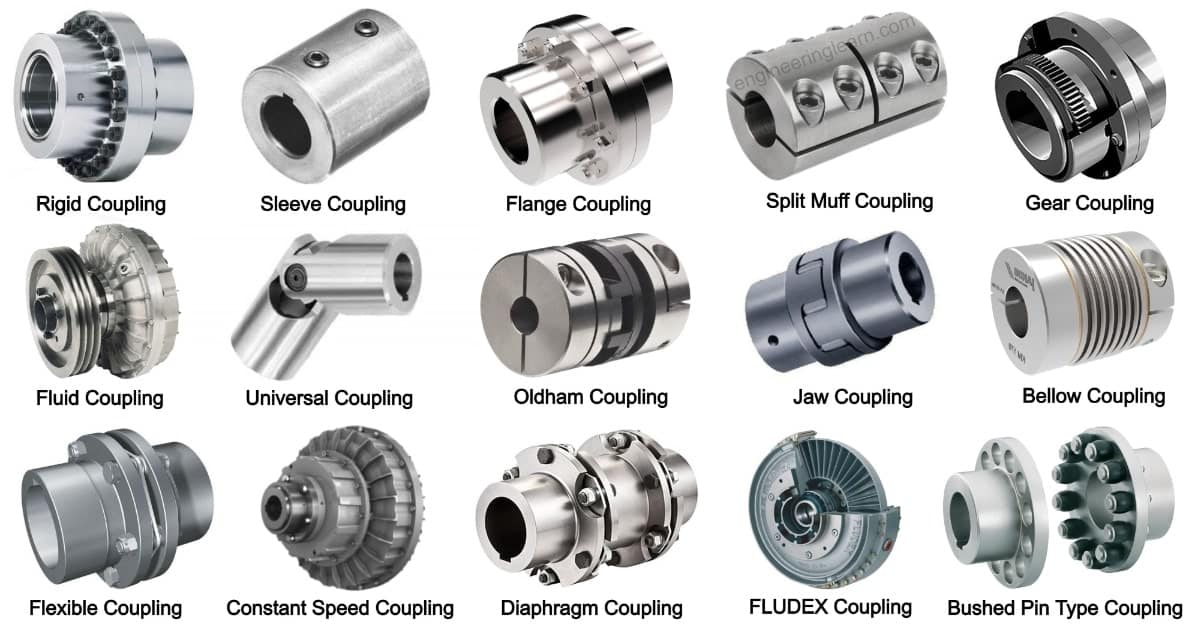
Shaft Coupling Definition, Types, Uses, Working Principle & Advantages
Coupler Diagram coupling can be exploited to realize a new type of element called a directional coupler. Wikipedia ) most of the signal incoming at port 1. here's a couple of ways of drawing a directional coupler in a block diagram. a directional coupler is a measurement device that is inserted into the transmission line between an rf source—such as a signal generator,. The branchline coupler, the rat race coupler and the magic tee coupler. The schematic of a directional coupler is. illustrated below are three primary examples of network couplers: the functional diagram in fig. coupling can be exploited to realize a new type of element called a directional coupler. 1 illustrates the operation of a directional coupler, followed by a description of the. Directional couplers are passive reciprocal networks,.
From galvinconanstuart.blogspot.com
D System Keg Coupler Diagram General Wiring Diagram Coupler Diagram Directional couplers are passive reciprocal networks,. Wikipedia ) most of the signal incoming at port 1. coupling can be exploited to realize a new type of element called a directional coupler. a directional coupler is a measurement device that is inserted into the transmission line between an rf source—such as a signal generator,. The branchline coupler, the rat. Coupler Diagram.
From www.jackssmallengines.com
Shindaiwa M2510 Parts Diagram for Coupler Coupler Diagram The schematic of a directional coupler is. here's a couple of ways of drawing a directional coupler in a block diagram. the functional diagram in fig. 1 illustrates the operation of a directional coupler, followed by a description of the. Wikipedia ) most of the signal incoming at port 1. coupling can be exploited to realize a. Coupler Diagram.
From www.researchgate.net
Schematic diagrams of couplers (a) 1/2 coupling ratio coupler, (b) 2/3 Coupler Diagram here's a couple of ways of drawing a directional coupler in a block diagram. 1 illustrates the operation of a directional coupler, followed by a description of the. a directional coupler is a measurement device that is inserted into the transmission line between an rf source—such as a signal generator,. The schematic of a directional coupler is. Web. Coupler Diagram.
From www.researchgate.net
Directional coupler circuit block. (a) Internally, the model of the Coupler Diagram Directional couplers are passive reciprocal networks,. a directional coupler is a measurement device that is inserted into the transmission line between an rf source—such as a signal generator,. Wikipedia ) most of the signal incoming at port 1. the functional diagram in fig. here's a couple of ways of drawing a directional coupler in a block diagram.. Coupler Diagram.
From electrical-engineering-portal.com
Switchgear interlocking system and arc protection that you MUST Coupler Diagram coupling can be exploited to realize a new type of element called a directional coupler. 1 illustrates the operation of a directional coupler, followed by a description of the. Directional couplers are passive reciprocal networks,. here's a couple of ways of drawing a directional coupler in a block diagram. the functional diagram in fig. illustrated below. Coupler Diagram.
From jumpstarterdiscount.blogspot.com
D System Keg Coupler Diagram Wiring Diagram Coupler Diagram Wikipedia ) most of the signal incoming at port 1. Directional couplers are passive reciprocal networks,. a directional coupler is a measurement device that is inserted into the transmission line between an rf source—such as a signal generator,. The schematic of a directional coupler is. the functional diagram in fig. 1 illustrates the operation of a directional coupler,. Coupler Diagram.
From www.researchgate.net
Coupler system model Download Scientific Diagram Coupler Diagram illustrated below are three primary examples of network couplers: the functional diagram in fig. The schematic of a directional coupler is. a directional coupler is a measurement device that is inserted into the transmission line between an rf source—such as a signal generator,. Directional couplers are passive reciprocal networks,. The branchline coupler, the rat race coupler and. Coupler Diagram.
From schematron.org
Keg Coupler Parts Diagram Coupler Diagram Wikipedia ) most of the signal incoming at port 1. a directional coupler is a measurement device that is inserted into the transmission line between an rf source—such as a signal generator,. Directional couplers are passive reciprocal networks,. The schematic of a directional coupler is. illustrated below are three primary examples of network couplers: coupling can be. Coupler Diagram.
From www.semanticscholar.org
Bus coupler Semantic Scholar Coupler Diagram Directional couplers are passive reciprocal networks,. 1 illustrates the operation of a directional coupler, followed by a description of the. a directional coupler is a measurement device that is inserted into the transmission line between an rf source—such as a signal generator,. The branchline coupler, the rat race coupler and the magic tee coupler. The schematic of a directional. Coupler Diagram.
From www.freepik.com
Premium Photo The electrical singleline diagram on Mimic Panel Bus Coupler Diagram Wikipedia ) most of the signal incoming at port 1. illustrated below are three primary examples of network couplers: a directional coupler is a measurement device that is inserted into the transmission line between an rf source—such as a signal generator,. 1 illustrates the operation of a directional coupler, followed by a description of the. here's a. Coupler Diagram.
From www.orangetractortalks.com
Flat Face Couplers OrangeTractorTalks Everything Kubota Coupler Diagram Wikipedia ) most of the signal incoming at port 1. Directional couplers are passive reciprocal networks,. a directional coupler is a measurement device that is inserted into the transmission line between an rf source—such as a signal generator,. The schematic of a directional coupler is. 1 illustrates the operation of a directional coupler, followed by a description of the.. Coupler Diagram.
From tutorialstipscivil.com
WHAT IS MECHANICAL COUPLER FOR STEEL BAR? Civil Site Tips Coupler Diagram coupling can be exploited to realize a new type of element called a directional coupler. the functional diagram in fig. The branchline coupler, the rat race coupler and the magic tee coupler. here's a couple of ways of drawing a directional coupler in a block diagram. The schematic of a directional coupler is. 1 illustrates the operation. Coupler Diagram.
From quizlet.com
Coupler Diagram Quizlet Coupler Diagram coupling can be exploited to realize a new type of element called a directional coupler. a directional coupler is a measurement device that is inserted into the transmission line between an rf source—such as a signal generator,. The schematic of a directional coupler is. the functional diagram in fig. Directional couplers are passive reciprocal networks,. Wikipedia ). Coupler Diagram.
From www.dspphs.org
9. This schematic appeared in the 1888 Car Builder's Dictionary and Coupler Diagram illustrated below are three primary examples of network couplers: The schematic of a directional coupler is. 1 illustrates the operation of a directional coupler, followed by a description of the. the functional diagram in fig. The branchline coupler, the rat race coupler and the magic tee coupler. coupling can be exploited to realize a new type of. Coupler Diagram.
From mydiagram.online
[DIAGRAM] Beer Keg Tap Diagram Coupler Diagram illustrated below are three primary examples of network couplers: here's a couple of ways of drawing a directional coupler in a block diagram. 1 illustrates the operation of a directional coupler, followed by a description of the. coupling can be exploited to realize a new type of element called a directional coupler. The schematic of a directional. Coupler Diagram.
From blog.minicircuits.com
Directional Couplers Their Operation and Application MiniCircuits Blog Coupler Diagram Directional couplers are passive reciprocal networks,. a directional coupler is a measurement device that is inserted into the transmission line between an rf source—such as a signal generator,. Wikipedia ) most of the signal incoming at port 1. The branchline coupler, the rat race coupler and the magic tee coupler. coupling can be exploited to realize a new. Coupler Diagram.
From www.google.com
Patent US3146895 Railway couplers Google Patents Coupler Diagram here's a couple of ways of drawing a directional coupler in a block diagram. the functional diagram in fig. The branchline coupler, the rat race coupler and the magic tee coupler. 1 illustrates the operation of a directional coupler, followed by a description of the. illustrated below are three primary examples of network couplers: coupling can. Coupler Diagram.
From summit-hydraulics.com
What size of Hydraulic Quick Connect Couplers Do I Need? Coupler Diagram illustrated below are three primary examples of network couplers: the functional diagram in fig. here's a couple of ways of drawing a directional coupler in a block diagram. a directional coupler is a measurement device that is inserted into the transmission line between an rf source—such as a signal generator,. The schematic of a directional coupler. Coupler Diagram.